Lab 5: Interrupts
Introduction
Building off what was learned in the previous Lab 4, three interrupts were interfaced with both the MCU’s internal system clock a timer to perform a constant polling of the pulses produced by a given motor’s quadrature encoder. This information was then converted into an angular velocity by computing a running average over the sampling period, the value of which was then subsequently printed out in the built-in Segger Debug mode terminal, along with the motor’s direction of rotation. Additionally, the written output was configured to auto-update at least every second.
Design and Testing Methodology
Firstly, the PLL was configured to take in the multispeed internal (MSI) RC oscillator as an input and output an 80 MHz clock signal. Then, pins PA9 and PA10 were set up to take the outputs of the quadrature encoder as inputs, while timer TIM16 was configured to dictate a sampling period of one second. Finally, three different interrupts were enabled, with two tied to PA9 and PA10, respectively, and the last being connected to TIM16; more specifically, the two external interrupts were coded to trigger on every rising and falling edge of the encoder pulses, so as to get the best resolution possible, while the timer interrupt was asserted with the raising of the Update Interrupt Flag in software, which occurred every one second. (Note that some files were not originally produced and were instead taken from the solutions branch of an in-class activity.)
Various tests were conducted on the final product, including both physical interaction with the resultant circuit and manual polling, as elaborated on in a later Results and Discussion section.
Technical Documentation
The source code for this project can be found in the associated GitHub repository folder.
Schematic

The Figure 1 schematic outlines how the physical components actually connect. PA9 and PA10 were chosen as inputs because they are 5V-tolerant. Note that both quadrature encoders comprise Hall Effect sensors.
Flowchart
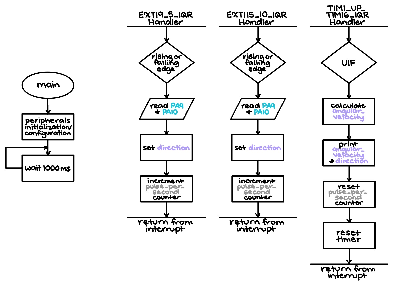
Additionally, a flowchart illustrating the main steps of the program and function calls can be viewed in Figure 2 above. Because the heavier, calculation-oriented work was done entirely in the three interrupt handlers, the main function does not seemingly comprise much substance.
Mathematical Verification
The speed measured by the MCU can also be mathematically verified to match the true motor speed and direction, as shown in Figure 3 below:
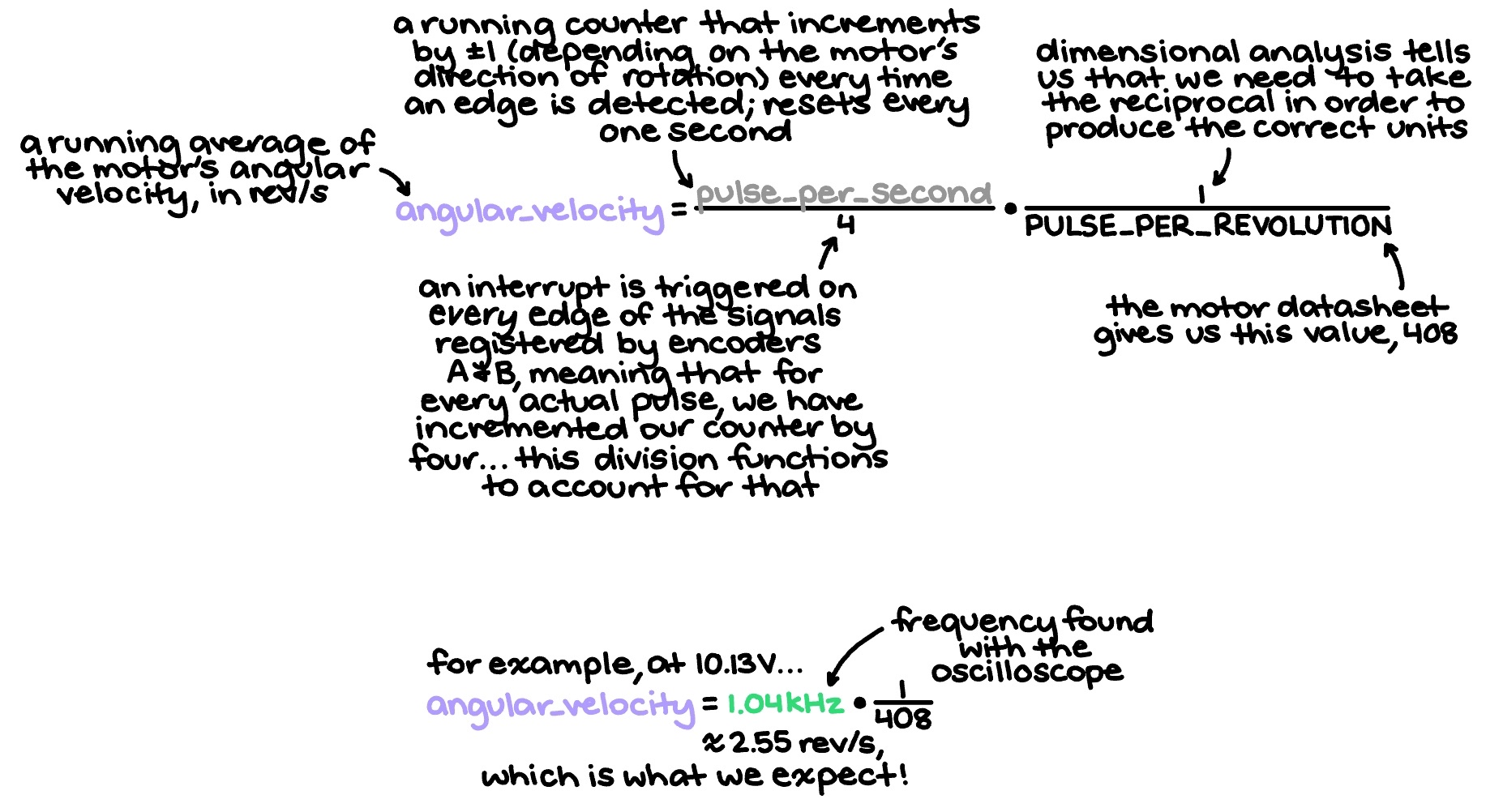
In short, the measured speed displayed was a running average of the total detected pulse edges over a one-second period, the counter for which was incremented by positive one if the motor was turning clockwise and negative one if it was going counterclockwise (no motor movement simply resulted in the counter maintaining its previous value). When given a voltage for which the motor’s actual speed was known, the frequency of PA10 was determined using an oscilloscope and subsequently converted into an angular velocity, so as to provide a more direct and obvious point of comparison.
Results and Discussion
The results of Lab 5 are shown in Figure 4, as follows:
Evidently, the design performed adequately and exactly to spec. At approximately 10 V, the measured angular velocity was around 2 rev/s, as expected. Furthermore, this velocity value demonstrably had a direct relationship with voltage (as intended), the printed direction of rotation was always accurate, and the terminal very visibly updated at a rate 1 Hz.
Manual Polling
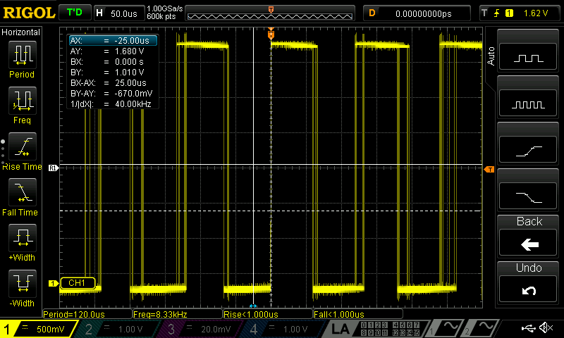
Figures 5a and 5b depict the frequencies at which the MCU is able to toggle a GPIO pin in an empty while loop and a loop that prints an incremented value, respectively.
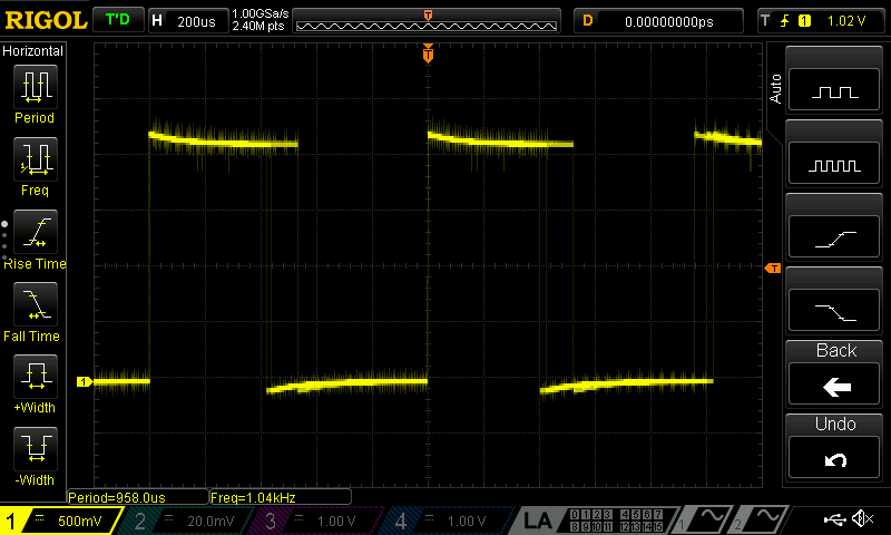
Meanwhile, Figure 6 displays the actual pulse frequency received from quadrature encoder B by PA10 (and its attached interrupt handler) when the motor is being supplied 10.13 V; this is the signal that is actually being detected in this lab, and used for all calculations mentioned above.
Now, in order to compare the performance of interrupts as opposed to manual polling in this specific situation, a few calculations were made in Figure 7 below:

In essence, it is always better to use interrupts when it comes to high-speed sampling, though for the sake of this lab, manual polling does not actually perform all that horribly.
Conclusion
All in all, the design utilized three different interrupts to detect rising and falling edges from the two quadrature encoders’ output pulses, accurately extrapolated the motor’s angular velocity and rotational direction from that information, and printed such in the Debug terminal at a rate of at least 1 Hz. A total of approximately 15 hours was spent on this lab.
AI Prototype
Using ChatGPT to generate some code in response to the prompt “Write me interrupt handlers to interface with a quadrature encoder. I’m using the STM32L432KC, what pins should I connect the encoder to in order to allow it to easily trigger the interrupts?,” the LLM produced rather inaccurate results that can be viewed in the public chat transcript. When trying to build its output code, the error message depicted in Figure 8 was produced.
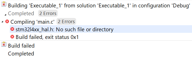
The fact that the AI could not even include the correct header file was indicative of a greater issue at hand — the fact that it could write mostly accurate lines in isolation, but not stitch them together in a way that was usable. Technically, its syntax was correct, but it did not have a good enough understanding of the bigger picture to create something that was properly interfaced.
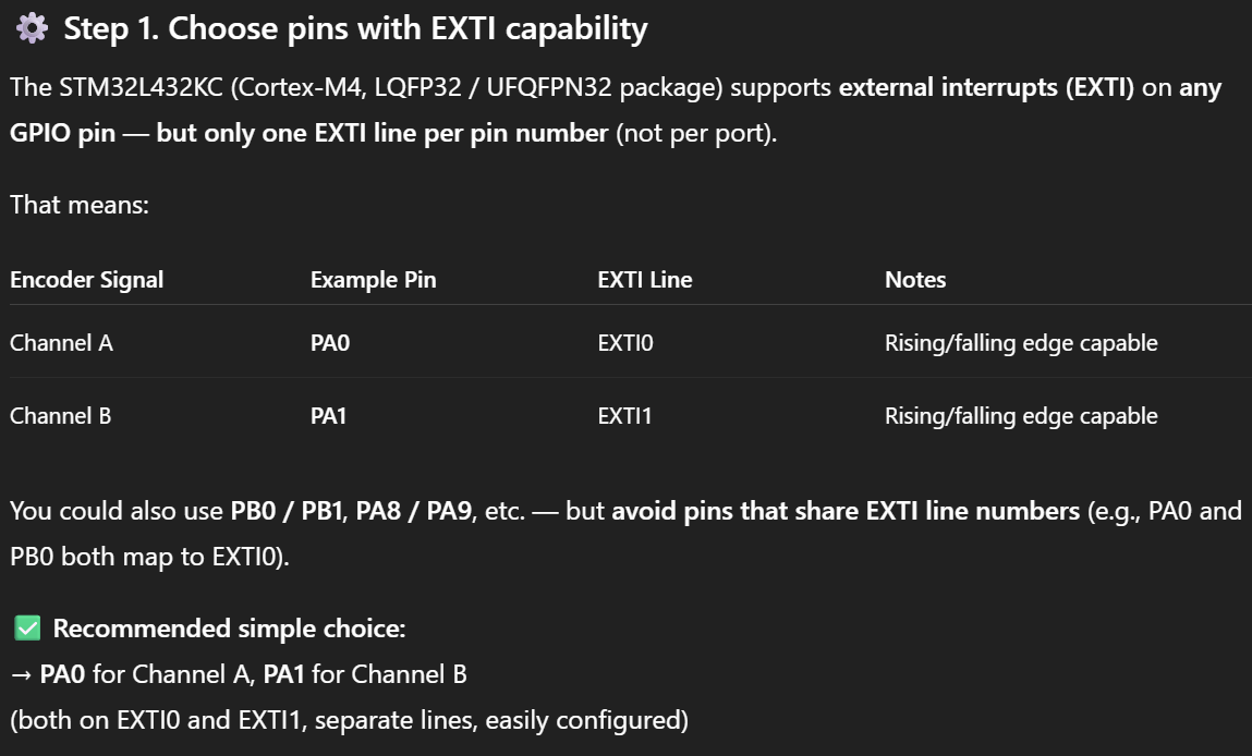
However, when it came to simply offering advice and not code, the LLM performed much better. For example, in Figure 9, two usable, 5V-tolerant pins were, in fact, recommended.
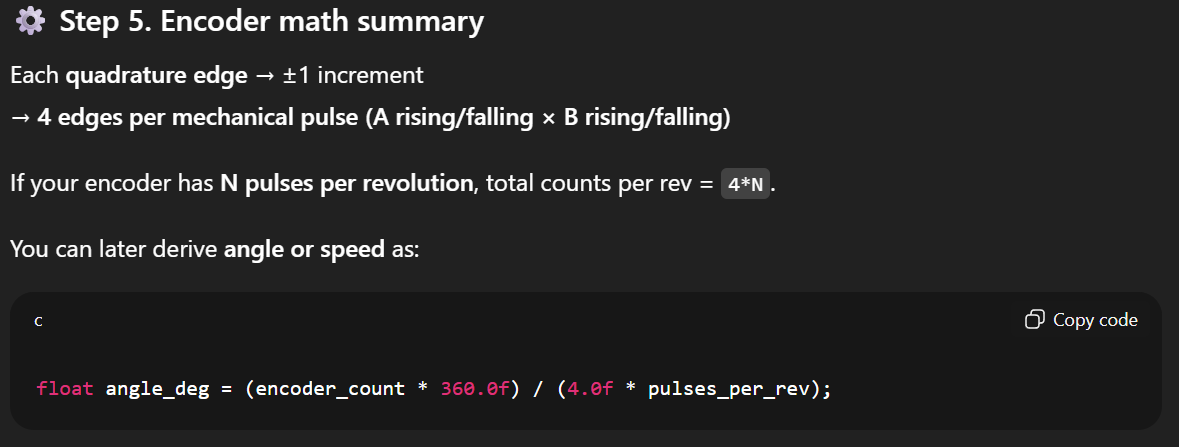
Moreover, although the AI decided to solve for angular degrees instead of angular velocity, it did output the correct equation for doing so, as shown in Figure 10. However, once again, this line of code only existed in isolation, without any real clarity regarding where to declare it and when it use it.
Thus, in summary, the LLM for this week’s AI prototype produced solidly middling results. If perhaps given more instruction as to how the user wants their prompt to be answered, it would likely perform better, but in the meantime, it seems to require significant understanding of interrupts and the task at hand to comprehend what it is trying to do.