Lab 6: The Internet of Things and Serial Peripheral Interface
Introduction
In this lab, the MCU was interfaced with both a DS1722 temperature sensor and an ESP8266 WiFi development board in order to display the output of the former (in Celsius) on a webpage, with the information updating every time the site was refreshed. Additionally, interaction with the page’s buttons allowed the user to manually set the sensor’s resolution to any integer value between eight and 12, as well as toggle an on-board LED and report its status accordingly. Thus, in brief, the aim of this assignment was to design and create an Internet of Things device. Furthermore, the Logic Analyzer function on one of the lab oscilloscopes was used to prove that proper SPI transactions were actually occurring.
Design and Testing Methodology
Firstly, the MCU’s SPI peripheral was configured to allow communication with the temperature sensor, with the MCU as the controller and the temperature sensor as the peripheral. Following the configuration guidelines/restrictions outlined in the sensor’s datasheet baud rate of 5 MHz, clock polarity of zero (corresponding to an idle clock signal of zero, according to the MCU’s own reference manual), and a clock phase of one (which set the first data capture edge to the clock’s second transition). Moreover, the sensor was set to continuously poll. Pins PB0 and PB3 were used to output the chip select and clock signals, respectively, while the SDO and SDI signals were tied to PB4 and PB5.
Next, the UART/USART protocol was enabled to talk to the ESP8266 unit. All of the webpage’s contents were written in HTML and sent from the MCU to the WiFi development device by tying the former’s receiver pin, PA9, to the latter’s TX and the transmitter pin PA10 to RX. Finally, PA6 was configured as the toggle-able on-board LED. (Note that some files were not originally produced and were instead taken from the starter code provided by the teaching team.)
Various tests were conducted on the final product, including both physical interaction with the resultant circuit and oscilloscope traces, as elaborated on in a later Results and Discussion section.
Technical Documentation
The source code for this project can be found in the associated GitHub repository folder.
Schematic
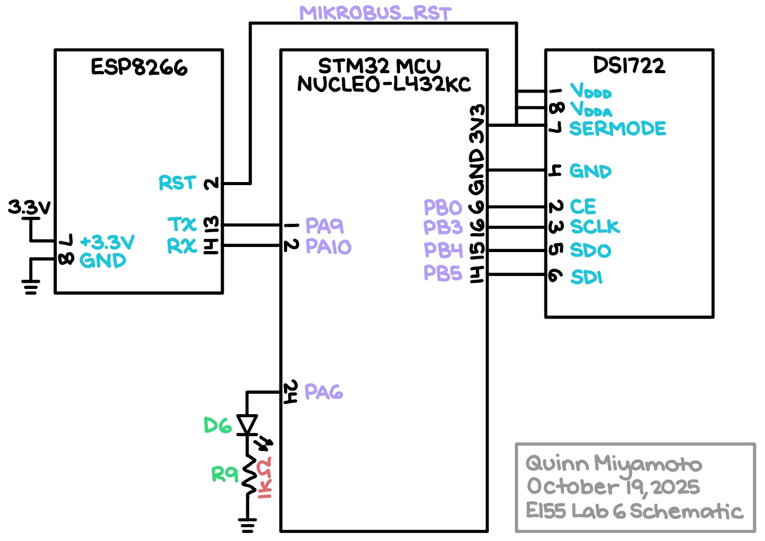
The Figure 1 schematic outlines how the physical components actually connect. Note that the temperature sensor’s SERMODE, which sets the serial interface mode through hardware, was hooked up to power in order to enable SPI communication (as opposed to a standard 3-wire data transfer). All SPI-related pins were chosen from GPIO Port B’s selection so that they would not interfere with the UART/USART pins tied to GPIO Port A.
Results and Discussion
The results of Lab 6 are shown in Figure 2, as follows:
As can clearly be seen in the video above, the design performs well and meets all of the required specs; in response to heat being applied to the temperature sensor via someone’s finger, the website displayed reasonable results with appropriate incrementing. However, one point of improvement would be to mitigate the need to click twice on a given resolution button in order to actually receive the desired temperature reading.
E155 Online LED Toggler and Temperature Reporter Webpage

The screenshot depicted in Figure 3 provides an example of what the actual webpage, hosted at 192.168.4.1, would look like if the “LED: Off” and “Resolution: 12” buttons were pressed. Note that resolutions eight through twelve correspond to actual temperature resolutions of 1.0 °C, 0.5 °C, 0.25 °C, 0.125 °C, and 0.0625 °C, respectively.
Logic Analyzer Traces
In order to verify that the MCU and temperature sensor were interfacing over SPI as intended, the oscilloscope’s Logic Analyzer function was used to capture the states of the SCLK, MISO (SDO), and MOSI (SDI) signals during a single pulse of the CE signal. Figure 4a shows the MCU first forcing the sensor into Write mode with the 0x80 address before immediately telling it to set a 12-bit resolution with 0xEE, while Figure 4b depicts the sensor entering Read mode twice — with both the 0x02 and 0x01 addresses — to fetch the information stored in both the MSB and LSB. All in all, the appearance of the expected addresses being sent over SDO and SDI evidences the existence of proper SPI communication.
Conclusion
Overall, the design used both the SPI and UART/USART protocols to enable communication between the MCU, temperature sensor, and WiFi development board, and successfully displayed a live, updatable report of the temperature with user-adjustable resolution online, along with the status of an on-board LED. A total of approximately 12 hours was spent on this lab.
AI Prototype
Using ChatGPT to generate some code in response to the prompt “I’m making a web portal to interface with a temperature sensor. Create a HTML page that looks good and is intuitive to show the temperature, control an LED, and change the precision of the readout,” the LLM produced surprisingly attractive results that can be viewed in the public chat transcript, as well as in Figure 5 below:
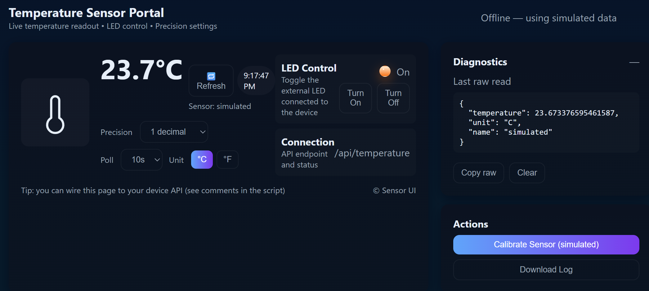
Admittedly, the aesthetics of the AI-generated website were superior to that of the website created in this project; in the simulation the LLM provided, it also appeared to be relatively functional. For future projects, it might be worth using AI to help with design choices pertaining to aesthetics.
However, in response to the second prompt “Write me a C function to carry out a SPI transaction to retrieve a temperature reading from a DS1722 sensor. Make use of CMSIS libraries for the STM32L432KC,” ChatGPT produced the code visible in a public chat transcript that ultimately did not work. The resultant error message can be seen in the following Figure 6:

Even with further prompting to fix the problem, ChatGPT was not able to properly identify the issue. An attempt was made to add the newly generated functions to the header file to see if that would make a difference, but it did not. Thus, in summary, because the LLM did not provide the necessary main and header files, it was unhelpful in this sort of situation and made things less clear on the whole.